

Что такое быстрое прототипирование?
Чтобы сохранить и увеличить конкурентоспособность, производители стремятся выводить продукцию на рынок в минимальные сроки. Как достичь этой цели? Один из способов – сократить цикл разработки продукта.
Прототипирование, будучи ключевым этапом разработки, – процесс достаточно трудоемкий: чтобы понять, какое решение будет наиболее эффективным, потребуется длительный этап проектирования и доработок с выполнением ряда итераций.
Для достижения наилучших результатов эту стадию нужно завершать как можно раньше. Быстрое прототипирование, то есть создание прототипов посредством 3D-печати, позволяет существенно сократить цикл разработки и сэкономить ресурсы.
3D-технологии помогают сократить весь процесс, начиная с формулировки идеи до создания физического объекта, до нескольких часов. Быстрое прототипирование дает возможность улучшить и экономические показатели: экономится не только время на разработку, но и трудовые затраты.
(pdf) rapid-prototyping of iterative learning control using matlab/simlink hybrid-programming
Rapid-Prototyping of Iterative Learning Control Using
MATLAB/Simlink Hybrid-Programming
Yongqiang Ye, Abdelhamid Tayebi,and Xiaoping Liu
Abstract— Rapid-control-prototypingisanefficientmeanof
experimental study for control research. It is a challenge to
exercise rapid-control-prototyping for iterative learning control
(ILC) due to the finite time nature of ILC. This paper
describes the construction of an ILC system based on MATLAB,
Simulink, and Quanser WinCon. MATLAB/Simulink hybrid-
programming is utilized to solve the complex task of rapid-
prototyping for ILC. The built robotic system has been shown
an effective testbed for ILC. The project can provide control
students a good opportunity to gain hands-on proficiency with
MATLAB/Simulink hybrid-programming, rapid-prototyping,
and ILC.
I. INTRODUCTION
The term rapid-control-prototyping is used to describe
quick control algorithms development and testing. Design
tools such as Simulink enable control engineers to design
controllers directly in block diagrams. Real-time code is gen-
erated from block diagrams and implemented on hardware.
Control engineers can record data histories in real time and
change parameters online. These tasks are performed during
early development so that overall development costs are
lowered. Therefore rapid-control-prototyping is an efficient
mean in control research.
Iterative learning control (ILC) [1], [2], [3], [4] is a
suitable technique for uncertain systems that operate in a
repetitive manner. It aims to iteratively reduce the tracking
error, over a finite time interval, by incorporating past
experience in the actual control input. Given a desired output
trajectory yd(k)for a fixed operation period T=[0,N],
except the current-cycle ILC [5], a general previous-cycle
ILC law can be represented in discrete-time form as
uj(k)=uj−1(k) ΓL(ej−1(τ)),(1)
where uj(k)is the input at iteration j,τ∈[0,N], and
ej−1(τ)=yd(τ)−yj−1(τ).yj−1(τ)is the output at iteration
j−1,L(·)is a function selected by the designer, and Γis
a scalar learning gain to adjust learning speed. Numerous
learning laws can be found in the survey papers of [6], [7],
[8] and references therein.
Simple control simulation tasks can be implemented in
MATLAB script or Simulink alone. However, ILC is rel-
atively complex in the sense of programming. Hybrid-
programming of MATLAB script and Simulink is used to
Y. Ye is with College of Automation Engineering, Nanjing University
of Aeronautics and Astronautics, Nanjing, Jiangsu 210019, China. He had
been with the Department of Electrical Engineering, Lakehead University,
Thunder Bay, Ontario P7B 5E1, Canada melvinye@nuaa.edu.cn
Abdelhamid Tayebi and Xiaoping Liu are with the Department of
Electrical Engineering, Lakehead University, Thunder Bay, Ontario P7B
5E1, Canada atayebi,xiaoping.liu@lakeheadu.ca
solve complex simulation tasks that Simulink alone has
difficulty to handle. Therefore, hybrid-programming of MAT—
LAB script and Simulink can be adopted to implement ILC.
This paper describes the construction of and ILC experi-
mental setup. In the project, ILC is carried out on a Quanser
open architecture CRS A465 robot. Quanser WinCon [9]
based rapid-prototyping is adopted in the project. A solution
of MATLAB and Simulink hybrid-programming is given to
meet the implementation challenge of ILC.
After finishing the project, an in-depth knowledge of MAT—
LAB/Simulink hybrid-programming and rapid-prototyping
can be gained. Moreover, the described project is an effective
educational demonstrator of ILC to control students.
II.FEATURES OF ILC
As shown in Fig. 1, ILC can be divided into two phases
running alternately and continuously. One phase is the ex-
Fig. 1.Two phases of ILC.
ecution of a command, which is usually an implementation
of feedback control, and the other is the command update
phase where ILC algorithm (1) is performed.
Compared with classical feedback control, ILC has three
major differences.
1)First, the execution of one iteration of ILC is over finite
time, whereas classical feedback control is typically
over infinite time.
2)Second, errors of past cycles are already available for
the command update of next iteration.
3)Third, the plant is designed to return to a same initial
condition before a new iteration begins.
One can conclude that ILC schemes are based on a batch
update, and the generation of the control input to be applied
§
Advantages of rapid prototyping
The whole purpose of innovation in industrial technology is maximising revenue through more effective ways of manufacturing. There are a few different perks rapid prototyping brings to the table to lower costs, enhance speed and time-to-market.
Applications
Product designers use this process for rapid manufacturing of representative prototype parts. This can aid visualisation, design and development of the manufacturing process ahead of mass production.
Originally, rapid prototyping was used to create parts and scale models for the automotive industry although it has since been taken up by a wide range of applications, across multiple industries such as medical and aerospace.
Rapid tooling is another application of RP, whereby a part, such as an injection mould plug or ultrasound sensor wedge, is made and used as a tool in another process.
Binder jet 3d printing
Another rapid prototyping and additive manufacturing technology.
Here, an inkjet print head deposits liquid binding material onto the last layer of the part. After it’s done, a new layer is formed by spreading powder material onto the binding liquid. As it solidifies, it forms another layer.
The biggest problem with this kind of rapid prototyping technology is wasting of the powder material. While some of the excess material can be reused, there are limitations to the number of times it can be done.
Also, some of the excess material has to be thrown away right after the first manufacturing cycle is complete.
Communication of ideas
To be fair, CAD software itself already took a great leap forward from engineering drawings. You can change the part design with a few clicks, rotate it, find assembly interferences and move the assembly as you like. But it is not the same as real life..
Actually touching and playing around with a product still in the concept phase can clearly bring forth the shortcomings and spark some more inspiration. Also, others will be able to see your vision in action.
Sometimes, such visualisation may also be a deal-maker when pitching a solution to a customer or an investor.
Functionality of prototypes
Rapid prototyping offers a wide range of methods to bring your design ideas to life. 3D printers are the fastest way to get a tangible result. At the same time, the choice of method depends largely on the purpose of prototyping in your product development process.
All the 3D printing methods come with different levels of quality. But a nice result is obtainable through some post-processing.
For non-structural parts, plastic is probably more than good enough to prove the functionality and/or design features in case of a pair of glasses, for example. Structural parts need to be able to bear loads. And this is where substituting metal for another material is not reasonable.
Although 3D printing is also available for metal, it is still hard to find a service at a viable cost because today, the machines with such capabilities are few and far between.
Until the price-point lowers, the most convenient way to test out some ideas for metal parts in the product development process is by using CNC machining and other metal fabrication services online.
Fused deposition modelling (fdm)
Also known as fused filament fabrication, this is the most common form of 3D printing. The majority of hobbyists looking to produce their prototyping design concepts use this type of rapid prototyper machines.
It uses a continuous thermoplastic filament to create the parts. During the process, the filament is heated at the nozzle or extruder head.
CNC-controlled motors move the head during printing according to the input. The surface finish of the parts is not as good as with many of the other processes, but the popularity of the method stems from its affordability.
3D printed objects created by fused deposition modelling may also require support structures in the case of a more complex design with overarching features. These are usually removed during post-processing.
Fused deposition modelling (fdm) or material jetting
This inexpensive, easy-to-use process can be found in most non-industrial desktop 3D printers. It uses a spool of thermoplastic filament which is melted inside a printing nozzle barrel before the resulting liquid plastic is laid down layer-by-layer according to a computer deposition program.
How to incorporate rapid prototyping ideas during the design phase?
If possible, the test product can be simplified for cost-effective production. For example, a test product may replace tapped holes with regular holes as it is easier to produce but does not, in some cases, affect the functionality of the part.
Is rapid prototyping the same as 3d printing?
Making rapid prototypes is only one way of using 3D printing. Rapid prototyping also involves other methods, so they are definitely not synonymous.
Laminated object manufacturing
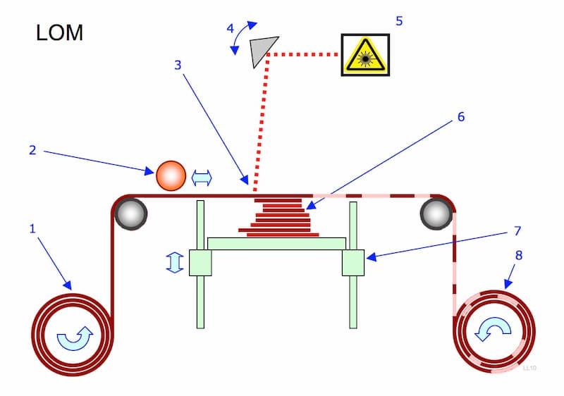
Laminated object manufacturing, or LOM for short, uses thermoplastic adhesives when stacking layers of sheet material on top of each other.
The sheet material has to reach certain temperatures first to activate the adhesive on top of the last layer. For that reason, a heated roller is placed just before the stack that ends up as the rapid proto part.
As soon as the new layer is in place, a laser beam cuts it into shape.
Laminated object manufacturing (lom) or sheet lamination
This inexpensive process is less sophisticated than SLM or SLS, but it does not require specially controlled conditions. LOM builds up a series of thin laminates that have been accurately cut with laser beams or another cutting device to create the CAD pattern design. Each layer is delivered and bonded on top of the previous one until the part is complete.
Online cnc machining
Now we come to the more traditional manufacturing methods. CNC machining is well suitable for prototyping parts from a variety of different materials, from metals to plastics.
Online sheet metal fabrication
Sheet metal fabrication has also moved online by now. While CNC machining may need a lot of setups over the course of producing a single part, laser cutting and bending a uniform thickness sheet is a little less complicated.
Online service providers often feed large datasets from manufacturing partners to the algorithms to arrive at reasonable market prices.
Sheet metal prototyping is a great way to aid the product development process by building the design as intended. This means you can make the parts with complex cutouts from the chosen material (e.g. S355 instead of a cardboard substitute) to also test the parts for the structural qualities in an assembly.
Price
The availability of these services online means that you do not have to spend time to produce the parts yourself while also minimising the activities related to outsourcing production.
In case of 3D printing, it is even viable to purchase a printer for in-house use because of the simultaneous advancements in technology and drop in machinery costs.
The automated nature of the whole manufacturing process also lowers the adjacent costs related to operating the machinery.
Quickness
Need the parts in under a week? No problem.
Small 3D printed parts can easily be created in a few hours. Here, the new process has significantly reduced the time spent on actual manufacturing.
In the case of CNC machining and laser cutting, the level of automation has had a great effect on overall speed and costs. The ability to process CAD files for automated pricing, machine setups and creating cutting programs is the driving force behind that change.
So whichever service you are going for, expecting the parts in less than a week is reasonable. This can definitely speed up the whole product-to-market cycle.
Rapid prototyping technology
We’ll start by pinpointing all the different additive manufacturing methods and then continue with more traditional ones like CNC machining and laser cutting, showing exactly how they can be used for rapid prototyping.
Selective laser melting (slm)
In essence, very similar to selective laser sintering (SLS). The main difference is in the materials – SLM, or direct metal laser sintering (DMLS) is suitable for metals.
Also, SLS does not need as high temperature for fusing the materials, whereas SLM actually needs the metal to melt in order to form stable bonds and a homogenous part.
Selective laser melting (slm) or powder bed fusion
Often known as powder bed fusion, this process is favoured for making high-strength, complex parts. Selective Laser Melting is frequently used by the aerospace, automotive, defence and medical industries. This powder bed based fusion process uses a fine metal powder which is melted in a layer by layer manner to build either prototype or production parts using a high-powered laser or electron beam. Common SLM materials used in RP include titanium, aluminium, stainless steel and cobalt chrome alloys.
Selective laser sintering (sls)
Also an additive manufacturing technology, selective laser sintering uses material powder and a high power laser to create the final part.
The laser beam heats the material to fuse the particles of plastic, glass, ceramic, etc. into a solid object with the desired shape. It also works on a layer-by-layer basis. After printing a layer, more material (about 0.1 mm) is added to form the next layer.
The SLS machine uses a pulsed laser because the density of the part depends on peak power output. The mass of powder is always in a heated state just below the fusing point.
One of the perks of using laser sintering is that there is no necessity for extra support. The part is always surrounded by loose material particles which secure the position and shape.
Stereolithography (sla)
A form of 3D printing technology that manufactures parts layer by layer using photochemical reactions.
Stereolithography, or resin printing, uses an ultraviolet laser that focuses on a vat of photopolymer resin. The 3D printers derive all the information from the CAD design, creating routes for the laser. Upon contact, the resin solidifies to form a layer of the rapid prototype.
Then, the part is submerged into resin again and the printing of another layer starts. After the process is complete, the parts must be cleaned from all the wet resin. Also, the cutting off of supportive structures for overhanging elements is necessary.
Stereolithography (sla) or vat photopolymerization
This fast and affordable technique was the first successful method of commercial 3D printing. It uses a bath of photosensitive liquid which is solidified layer-by-layer using a computer-controlled ultra violet (UV) light.
Testing
That’s the main purpose of producing rapid prototypes. You can test out a wide range of solutions in a short time-span to boost your product development towards a finished product that is actually reliable.
The ultimate guide to rapid prototyping for product development
Prototyping is a crucial part of the product development process, but traditionally, it has been a bottleneck.
Product designers and engineers would create makeshift proof-of-concept models with basic tools, but producing functional prototypes and production-quality parts often required the same processes as finished products. Traditional manufacturing processes like injection molding or CNC require costly tooling and setup, which makes low-volume, custom prototypes prohibitively expensive.
Rapid prototyping helps companies turn ideas into realistic proofs of concept, advances these concepts to high-fidelity prototypes that look and work like final products, and guides products through a series of validation stages toward mass production.
With rapid prototyping, designers and engineers can create prototypes directly from CAD data faster than ever before, and execute quick and frequent revisions of their designs based on real world testing and feedback.
In this guide, you’ll learn how rapid prototyping fits into the product development process, its applications, and what rapid prototyping tools are available to today’s product design teams.
Rapid prototyping is the group of techniques used to quickly fabricate a scale model of a physical part or assembly using three-dimensional computer-aided design (CAD) data. Because these parts or assemblies are usually constructed using additive fabrication techniques as opposed to traditional subtractive methods, the phrase has become synonymous with additive manufacturing and 3D printing.
Additive manufacturing is a natural match for prototyping. It provides almost unlimited form freedom, doesn’t require tooling, and can produce parts with mechanical properties closely matching various materials made with traditional manufacturing methods. 3D printing technologies have been around since the 1980s, but their high cost and complexity mostly limited use to large corporations, or forced smaller companies to outsource production to specialized services, waiting weeks between subsequent iterations.
The advent of desktop and benchtop 3D printing has changed this status quo and inspired a groundswell of adoption that shows no sign of stopping. With in-house 3D printing, engineers and designers can quickly iterate between digital designs and physical prototypes. It is now possible to create prototypes within a day and carry out multiple iterations of design, size, shape, or assembly based on results of real-life testing and analysis. Ultimately, the rapid prototyping process helps companies get better products to market faster than their competition.
Rapid prototyping elevates initial ideas to low-risk concept explorations that look like real products in no time. It allows designers to go beyond virtual visualization, making it easier to understand the look and feel of the design, and compare concepts side by side.
Physical models empower designers to share their concepts with colleagues, clients, and collaborators to convey ideas in ways not possible by merely visualizing designs on screen. Rapid prototyping facilitates the clear, actionable user feedback that is essential for creators to understand user needs and then refine and improve their designs.
Design is always an iterative process requiring multiple rounds of testing, evaluation, and refinement before getting to a final product. Rapid prototyping with 3D printing provides the flexibility to create more realistic prototypes faster and implement changes instantly, elevating this crucial trial and error process.
A good model is a 24-hour design cycle: design during work, 3D print prototype parts overnight, clean and test the next day, tweak the design, then repeat.
With 3D printing, there’s no need for costly tooling and setup; the same equipment can be used to produce different geometries. In-house prototyping eliminates the high costs and lead time associated with outsourcing.
In product design and manufacturing, finding and fixing design flaws early can help companies avoid costly design revisions and tooling changes down the road.
Rapid prototyping allows engineers to thoroughly test prototypes that look and perform like final products, reducing the risks of usability and manufacturability issues before moving into production.
Thanks to a variety of available technologies and materials, rapid prototyping with 3D printing supports designers and engineers throughout product development, from initial concept models to engineering, validation, and production.
Concept models or proof-of-concept (POC) prototypes help product designers validate ideas and assumptions and test a product’s viability. Physical concept models can demonstrate an idea to stakeholders, create discussion, and drive acceptance or rejection using low-risk concept explorations.
The key to successful concept modeling is speed; designers need to generate a wealth of ideas, before building and evaluating physical models. At this stage, usability and quality are of less importance and teams rely on off-the-shelf parts as much as possible.
3D printers are ideal tools to support concept modeling. They provide unmatched turnaround time to convert a computer file into a physical prototype, allowing designers to test more concepts, faster. In contrast with the majority of workshop and manufacturing tools, desktop 3D printers are office-friendly, sparing the need for a dedicated space.
As the product moves into the subsequent stages, details become increasingly important. 3D printing allows engineers to create high-fidelity prototypes that accurately represent the finished product. This makes it easier to verify the design, fit, function, and manufacturability before investing in expensive tooling and moving into production, when the time and cost to make change becomes increasingly prohibitive.
Advanced 3D printing materials can closely match the look, feel, and material characteristics of parts produced with traditional manufacturing processes such as injection molding. Various materials can simulate parts with fine details and textures, smooth and low-friction surfaces, rigid and robust housings, or soft-touch and clear components. 3D printed parts can be finished with secondary processes like sanding, polishing, painting, or electroplating to replicate any visual attribute of a final part, as well as machined to create assemblies from multiple parts and materials.
Engineering prototypes require extensive functional and usability testing to see how a part or assembly will function when subjected to stresses and conditions of in-field use. 3D printing offers engineering plastics for high-performance prototypes that can withstand thermal, chemical, and mechanical stress. The technology also provides an efficient solution for creating custom test fixtures to simplify functional testing and certification by gathering consistent data.
Having a great prototype is only half the battle; a design has to be repeatedly and economically manufacturable to become a successful final product. Design for manufacturability (DFM) balances the aesthetics and functionality of the design while maintaining the requirements of the end product. DFM facilitates the manufacturing process to reduce the manufacturing costs and keep the cost per part below the required level.
Rapid prototyping allows engineers to create small-batch runs, one-off custom solutions, and sub-assemblies for engineering and design validation (EVT and DVT) builds to test manufacturability.
3D printing makes it easier to test tolerances with the actual manufacturing process in mind, and to conduct comprehensive in-house and field testing before moving into mass production. 3D printed parts also support production, with prototyping tools, molds, jigs, and fixtures for the production line.
With 3D printing, design doesn’t have to end when production begins. Rapid prototyping tools allow designers and engineers to continuously improve products, and respond quickly and effectively to issues on the line with jigs and fixtures that enhance assembly or QA processes.
What is rapid prototyping?
And what is the difference between rapid prototyping and “just” prototyping?
Even the name itself says that rapid prototyping is a quick way for producing parts. And the speed is also the main difference between regular and rapid prototyping.
But it tells nothing about the reasons behind the boost in manufacturing speed.
Manufacturing plastic prototypes used to have the highest requirements for up-front investments. Creating a mould for injection moulding and actually producing something that functions, behaves and looks similar to the final product needed a lot of money.
Adding “rapid” into the mix needed a push in technological developments. Additive manufacturing in the form of 3D printing services has dramatically diminished the time and money necessary for producing a small batch of products or even a single part for an assembly.
Technologically, rapid prototyping for metal parts is also available through 3D printing. Still, the machinery with such capabilities is hard to find and the costs are considerably higher compared to CNC machining.
People also talk about CNC machining in the context of rapid prototyping. This refers to a few capabilities. For some time already, CAD/CAM software has been able to translate digital models into G code necessary for manufacturing. This development had a huge effect on costs and time requirements.
Задачи и сферы применения
3D-печать прототипов позволяет оптимизировать выполнение таких задач, как проектирование и модернизация модели, проверка на собираемость, визуальное представление детали или проекта, макетирование и тестирование для более оперативного запуска новых моделей.
С помощью 3D-принтера отдельно решается задача создания прототипов при изготовлении корпусов различных изделий для проверки на собираемость и функционального тестирования. Также возможна 3D-печать готовых корпусных изделий для применения на производстве.
Технология быстрого прототипирования применяется в следующих областях:
Быстрое прототипирование используется для изготовления как наглядных моделей, которые служат для визуализации идеи продукта и дают возможность оценить и усовершенствовать дизайн, так и функциональных прототипов, позволяющих ускорить реверс-инжиниринг и изготовление деталей, снятых с производства.
С помощью 3D-принтера можно быстро и экономично печатать прототипы обоих видов. 3D-печать помогает оперативно получить прототип с оригинала изделия или с CAD-модели. Точность печати обеспечивает максимальное соответствие изделий данным САПР, что обеспечивает высокое качество печати.
Благодаря многообразию термопластиков, композитов, полимеров, фотополимеров и других инновационных материалов для 3D-печати пользователь сможет создать изделие именно с теми физико-механическими свойствами и внешним видом, которые необходимы для решения конкретных задач.
Какие технологии и оборудование используются для 3d-печати прототипов
Для решения задач быстрого прототипирования в основном применяются следующие аддитивные технологии:
Наша компания предлагает широкий выбор оборудования для 3D-печати прототипов от ведущих производителей:
Примеры быстрого прототипирования
Задача: прототипирование компонентов гоночных мотоциклов с целью улучшить конструкцию, аэродинамику, а также комфорт гонщиков при подготовке к чемпионату мира MotoGP.
Сидоров и.а. rapid prototyping
Быстрое прототипирование (Rapid Prototyping — RP) — это процесс послойного построения физической модели (прототипа) в соответствии с геометрией 3D модели. БП — технология быстрого «макетирования», быстрого создания опытных образцов или работающей модели системы для демонстрации заказчику или проверки возможности реализации.
Термин используется как в информационных технологиях для обозначения процесса быстрой разработки программного обеспечения (см. RAD), так и в технологиях, связанных с изготовлением физических прототипов деталей. RAD (от англ. rapid application development — быстрая разработка приложений) — концепция создания средств разработки программных продуктов, уделяющая особое внимание быстроте и удобству программирования, созданию технологического процесса, позволяющего программисту максимально быстро создавать компьютерные программы.
Примерно с начала 1980-х начали интенсивно развиваться технологии формирования трёхмерных объектов не путём удаления материала (точение, фрезерование, электроэрозионная обработка) или изменения формы заготовки (ковка, штамповка, прессовка), а путём постепенного наращивания (добавления) материала или изменения фазового состояния вещества в заданной области пространства.
Некоторые из установок БП называют трёхмерными принтерами.
Основное отличие этой технологии от традиционных методов изготовления моделей заключается в том, что модель создается не отделением «лишнего» материала от заготовки, а послойным наращиванием материала, составляющего модель, включая входящие в нее внутренние и даже подвижные части.
Процессы построения в значительной степени автоматизированы и позволяют получать качественные и сравнительно недорогие модели, затрачивая на их изготовление часы, а не дни и недели, как это было при использовании традиционных методов. Использование технологий RP позволяет существенно сократить сроки и стоимость дизайнерских и конструкторских работ, работ по изготовлению технологической оснастки, а также повысить качество выпускаемой продукции.
Спектр применения получаемых по нашей технологии моделей: выставочные образцы, прототипы и промышленные образцы для проверки собираемости, конструкции и стиля. Также применяется для получения мастер моделей для тиражирования в силиконовых формах.
Изготовленные прототипы могут применяться в качестве замены моделей из воска для процесса литья по выплавляемым моделям. Сокращаются сроки изготовления и большие затраты на инструмент; модели из гипса обеспечивают повышенную точность, качество отделки поверхности и упрощают технологию вспомогательных операций.
Элементы прототипов могут быть изготовлены в виде готовой сборки. Минимальная толщина стенки может быть не менее 0,5 мм из соображений прочности.
Прототипирование является обязательным этапом в процессе разработки любого нового изделия. Создание качественного прототипа, максимально похожего на будущее изделие — весьма непростая задача. Приходится решать проблему точного повторения геометрической формы, собираемости, внешнего вида и поиска материалов, максимально похожих на заданные. Современный прототип позволяет не только оценить внешний вид детали, но и проверить элементы конструкции, провести необходимые испытания, изготовить мастер-модель для последующего литья. Использование RP-технологий в прототипировании способно на 50 — 80% сократить сроки подготовки производства, практически полностью исключить длительный и трудоемкий этап изготовления опытных образцов вручную, или на станках с ЧПУ.
Построение прототипа обычно происходит на основе твердотельной модели из CAD-систем или модели с замкнутыми поверхностными контурами. Эта модель разбивается на тонкие слои в поперечном сечении с помощью специальной программы, причем толщина каждого слоя равна разрешающей способности оборудования. Обычно при разбиении дается припуск на механическую обработку. Построение детали происходит послойно тех пор, пока не будет получен физический прототип.
Принципиальная схема всех установок прототипирования одинакова: на рабочий стол, элеватор установки, наносится тонкий слой материала, воспроизводящего первое сечение изделия, затем элеватор смещается вниз на один шаг и наносится следующий слой. Так слой за слоем воспроизводится полный набор сечений модели повторяя форму требуемого изделия. При этом на некотором слое может оказаться, что отдельные элементы «повисают» в воздухе, поскольку они должны крепиться к верхним слоям. Чтобы избежать такой проблемы, 3D модель предварительно подготавливается, в ней строится система поддержек на каждый такой элемент.
Основным различием между технологиями прототипирования является прототипирующий материал, а также способ его нанесения. В мире существует всего несколько компаний, изготавливающих RP-установки, они постоянно совершенствуют технологию и разрабатывают новые материалы.[1]
На данный момент значительного прогресса достигли технологии послойного формирования трёхмерных объектов по их компьютерным образам. Эти технологии известны под разными терминами, например, SFF (Solid Freeform Fabrication), FFFF (Fast Free Form Fabrication) или CARP (Computer Adied Rapid Prototyping), однако наибольшее стереолитография (STL — sterolithography); отверждение на твёрдом основании (SGC — Solid Ground Curing); нанесение термопластов (FDM — Fused Deposition Modelig); распыление термопластов (BPM — Ballistic Particle Manufacturing); лазерное спекание порошков (SLS — Selective Laser Sintering); моделирование при помощи склейки (LOM — Laminated Object Modeling); технология многосопельного моделирования (MJM Multi Jet Modeling) Иммерсионные центры, или системы виртуальной реальности.
Все названные технологии предполагают наличие трёхмерной компьютерной модели детали. Большинство известных САПР обеспечивают экспорт моделей в стандартном для быстрого прототипирования формате STL, или 3ds формат.[2]
Стереолитография (SLA — Stereo Lithography Apparatus)
Стереолитография является самым первым и наиболее распространенным методом прототипирования, во многом благодаря достаточно низкой стоимости прототипа. Принцип метода состоит в послойном отверждении жидкого фотополимера лазерным лучом, направляемым сканирующей системой. Элеватор находится в емкости с жидкой фотополимерной композицией, и после отверждения очередного слоя смещается вниз с шагом 0,025-0,3 мм. Используется достаточно твердый, но хрупкий полупрозрачный материал, подверженный короблению под влиянием атмосферной влаги. Материал легко обрабатывается, склеивается и окрашивается. Качество поверхностей без доводки хорошее.
Производители оборудования:
3D Systems www.3dsystems.com
F&S Stereolithographietechnik GmbH www.fockeleundschwarze.de
Институт проблем лазерных и информационных технологий РАН www.laser.ru
Технология SLS (Selective Laser Sintering — лазерное спекание порошковых материалов)
В SLS технологии в качестве рабочего материала используются порошковый пластик, металл или керамика, близкие по свойствам к конструкционным маркам. На поверхность наносится тонкий слой порошка, который затем спекается лазерным лучом, формируя твердую массу, соответствующую сечению 3D-модели и определяющую геометрию детали. SLS это единственная технология, которая может быть применена для изготовления металлических деталей и формообразующих для пластмассового и металлического литья. Прототипы из пластмасс обладают хорошими механическими свойствами, могут быть использованы для создания полнофункциональных изделий.
Производители оборудования:
3D Systems www.3dsystems.com
F&S Stereolithographietechnik GmbH www.fockeleundschwarze.de
The ExOne Company / Prometal www.prometal.com
EOS GmbH www.eos-gmbh.de.
Технология FDM (Fused Deposition Modeling — послойное наложение расплавленной полимерной нити)
Используются нити из АБС, поликарбоната или воска. Свойства используемых пластиков очень близки к конструкционным маркам. Термопластичный моделирующий материал подается через выдавливающую головку с контролируемой температурой, нагреваясь там до полужидкого состояния. Головка наносит материал очень тонкими слоями на неподвижное основание с высочайшей точностью. Последующие слои ложатся на предыдущие, отвердевают и соединяются друг с другом. Технология применяется для получения единичных образцов изделий, по своим функциональным возможностям приближенных к серийным, а также для производства выплавляемых моделей для литья металлов.
Производители оборудования:
Stratasys Inc. www.stratasys.com
Технология струйного моделирования (Ink Jet Modelling)
Различные запатентованные разновидности этой технологии называются:
MJM (Multi-Jet Modeling) — 3D Systems;
PolyJet (photopolymer jetting) — Objet Geometries;
DODJet (Drop-On-Demand-Jet) — Solidscape.
Все технологии имеют свои особенности, но функционируют по одному принципу. Головка, содержащая от двух до 96 сопел наносит модельный и поддерживающий материал на плоскость слоя. После нанесения слоя, могут проводится его фотополимеризация и механическое выравнивание. В качестве поддерживающего материала обычно используется воск, а в качестве модельного — широкий спектр материалов, очень близких по свойствам к конструкционным термопластам. Данный метод позволяет получать прозрачные и окрашенные прототипы с различными мехпническими свойствами — от мягких, резиноподобных до твердых, похожих на пластики.
Производители оборудования:
3D Systems www.3dsystems.com
Objet Geometries Ltd. www.2objet.com
Solidscape, Inc. www.solid-scape.com
Технология склеивания порошков (binding powder by adhesives)
Используются крахмально-целлюлозный порошок и жидкий клей на водяной основе, который поступает из струйной головки и связывает частицы порошка, формируя контур модели. По окончании построения излишки порошка удаляются. Для увеличения прочности модели, имеющиеся пустоты могут быть заполнены жидким воском. Такие технологии позволяют не просто создавать 3D-объекты произвольной формы, но еще и раскрашивать их.
Производители оборудования:
Z Corporation www.zcorp.com
Технология LOM (Laminated Object Manufacturing — ламинирование листовых материалов).
Слои прототипа создаются при помощи ламинирования бумажного листа. Контур слоя вырезается лазером, а поверхность, которую нужно затем удалить, режется лазером на мелкие квадратики. После извлечения детали мелко порезанные излишки материала легко удаляются. Структура полученного прототипа похожа на древесную, боится влаги.
Производители оборудования:
Helisys, Inc. — выпуск прекращен [3]
Преимущества технологий БП
• Сокращение длительности технической подготовки производства новой продукции в 2-4 раза.
• Снижение себестоимости продукции, особенно в мелкосерийном или единичном производстве в 2-3 раза.
• Значительное повышение гибкости производства.
• Повышение конкурентоспособности производства.
• Сквозное использование компьютерных технологий, интеграция с системами САПР.
Недостатки технологий БП
• Относительно высокая цена установок и расходных материалов.
• Невысокая точность
• Относительно низкая прочность моделей
С течением времени недостатки постепенно устраняются — снижаются цены, увеличивается выбор технологий и материалов.
Итоги: кратко
Время – самый дефицитный ресурс современного предприятия. Сэкономить время на изготовление и оценку физической модели продукта, сократить процесс разработки и воспользоваться изменениями на рынке для приобретения клиентов поможет быстрое прототипирование с использованием 3D-печати.
Широкие возможности аддитивных технологий и большой выбор оборудования и расходных материалов позволяют найти подходящее решение в самых разных областях применения и получить высокоточные и прочные модели в кратчайшие сроки.
Опытные эксперты компании iQB Technologies проконсультируют вас по вопросам, связанным с внедрением 3D-технологий, и предложат готовые 3D-решения для вашего предприятия, НИИ или вуза.
Похожее про Шкоду:
 Купить муфты компрессора кондиционера для Шкода Суперб (Skoda Superb) в Москве — цены, фото, OEM-номера запчастей | ФарПост
  Блок предохранителей и реле skoda oktavia, tour
  Сравнение автомобилей универсал BMW 3er E46 рестайлинг и седан Skoda Superb I
  купить по низкой цене, реле фар для Skoda Superb (3T4) в каталоге интернет магазина Купи Детали") Реле фар для Шкода Суперб (3T4) купить по низкой цене, реле фар для Skoda Superb (3T4) в каталоге интернет магазина Купи Детали
Реле фар для Шкода Суперб (3T4) купить по низкой цене, реле фар для Skoda Superb (3T4) в каталоге интернет магазина Купи Детали